Genie NZ Logic Relay Timers
![]()
Timers
· Useful to provide delay, prolong and control actions after a set period of time.
· It has a Reset Input, a Trigger Input and an Output that indicates Time-out.
There are 16 Timers available in AC and DC models .
Timers can be used as Contacts as well as Coils.
Notation:
In Genie-NX 'T' stands for Timer and Timer numbers are represented from 1 to 16. Thus T8 represents the eighth Timer. We refer the value of the nth Timer as Tn.
Timer Used as Contact:
Normally open (Tn) : In this type of contact TRUE value is valid.
· Normally closed. (tn) : In this type of contact FALSE value is valid.
Timer Used as Coil:
Trigger Input (TTn): In Timer functions trigger is required to start timer operation (Timer cycle). Reset Input (RTn): Reset Input is used to Reset the current Timer value to zero. The Trigger
contact is disabled and the block is ready for a new Timer cycle.
Note : If Reset and Trigger become true simultaneously then the Relay is Reset and the Timer does not run.
Timing:
Genie-NX allows different Timing ranges.:
S - Time value is specified in Seconds Maximum settable time is 999.9 s Resolution is 100 ms
Accuracy is +/-5 ms + Scan Time
M:S - Time value is specified in Minutes:Seconds
Maximum settable time is 99:59 M:S Resolution is 1 s
Accuracy is +/- 330 ms + Scan Time H:M - Time value is specified in Hours:Minutes Maximum settable time is 99:59 H:M
Resolution is 1 min
Accuracy is +/-20 s + Scan Time
Note :If Time preset value = 0 and Trigger is given then unpredictable operation may take place.This condition is shown as Program Error during program entry.
Locking:
Genie-NX Provides facility to "Lock" the parameters.
This means if a parameter is locked, user cannot change the values at the RUN time. In unlocked mode, effect of changing the time value in "RUN" Mode is as follows:
Case 1:
Time of timing relay is 000.0, trigger not received, and Reset not received. Set Time: 030.0 s
Enter and store new Time value: 020.0 s
Result --- Relay switches at 020.0 s after next trigger signal is received.
Case 2:
Trigger Input is given to Timer; no Reset, Time is running. Set Time: 030.0 s
Current Time: 010.0 s
Enter and store new Time value: 020.0 s
Result --- Relay switches at: 020.0 s
Case 3:
Trigger Input is given to Timer; Time has already elapsed, Reset not received. Set Time: 060.0 s
Current Time: 060.0 s
Enter and store new Time value: 080.0 s
Result: Timer Output remains active, 080.0 s is used for next Timer cycle.
Timer Functions:
There are 4 Types of Timer functions.:-
A: On Delay Timer. B: OFF Delay Timer.
C: Single Pulse Timer.
D: Symmetric/Asymmetric Timer. A: On Delay Timer:
Definition :
After receiving the Trigger Signal, the Relay Contact operates after Delay time (Make contact closes / Break contact opens after the Delay).

Application :Delay to Start a conveyor belt after a delay to ensure that the sensor is already active before the conveyor belt starts moving.
Ladder Diagram :
· I1 is used as start switch.
· T1 Timer is use in on Delay mode, value set is 10 s.
· Q1 is conveyor belt.

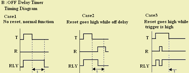
B: OFF Delay Timer:
Definition :
After Receiving the Trigger Signal, the Relay Contact operates immediately (Make contact closes / Break contact opens).It remains operated as long as the Trigger Input is present. The Timer starts when it detects that the Trigger Input is removed. The Relay Contact then switches after the Set Time
has expired (Make contact opens / Break contact closes).
Application:To ensure that motors, conveyor belts or ventilators etc. continue to function for a specified time after switching off the control signal.
Ladder Diagram :
· I1 is Power Switch
· T1 is OFF Delay Timer, Value set is 10 s
· Q1 is Conveyor belt

C: Single Pulse Timer:
Definition :
After receiving the Trigger Signal, the Make Contact closes (or Break Contact opens) for the specified time, Independently of Trigger present or not.

Application:
· Ringing school bell for specified time.
· Short impulses are lengthened and long impulses are shortened.
Ladder Diagram :
· I1 is power switch
· T1 is single pulse Timer for 10 s
· Q1 is school bell

D: Symmetric/Asymmetric Timer:
Definition :
The Relay Contact opens and closes for the Set Time Duration (Pulse Generator). The specified Time duration value may be Symmetric or Asymmetric.

Application:
Flashing of warning lamps, decorative lighting etc.
Ladder Diagram :
· I1 is push button.
· T1 is Symmetric/Asymmetric Timer for 1 s on 1 s off.
· Q1 is LED.

Timer Parameters:
1. Indication whether the timer is used in the program.
2. Timer lock status.
3. Preset time.
4. Inputs: Trigger and Reset, whether these are used as coils and will receive a signal.
5. Comment
6. Timer function.
You can select any one timer for viewing the properties.

 |